I have previously blogged about AVINetworks –> https://msandbu.wordpress.com/2016/02/19/a-closer-look-at-avi-networks/
Where I wrote briefly on how their scale-out architecture differs from their competitors, where most ADC vendors have a single virtual appliance which contains all the features + management. Avi networks consists of a Cloud Controller which is the management layer where we do management either using the UI or using REST APIs.
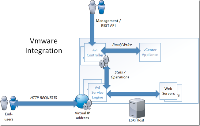
This example below shows an VMware architecture. The Avi Controller can either be a stand-alone virtual appliance or be configured in a 3 nodes controller cluster.
The Controller nodes can be setup with an integration with VMware with either read or read/write privileges. With read/write priviliges the Avi Controller can read and discover VMs, data centers, networks, and hosts. This also allows for automatic deployment of the service engine.
When we configure a virtual service, for instance an load balanced service for our web servers AVI will automatically deploy two SEs (Service Engines) based upon a OVA file. After the deployment there will be one active service engine and the other is passive, which will be responsible for serving the requests on the VIP.
Now the Service Engines also report server health, client connection statistics, and client-request logs to the Controllers, which share the processing of the logs and analytics information.
The cool thing with Avi is the auto-scaling feature! Now let’s say for instance if our Service Engines run out of resources, this might be CPU, Memory or the amount of packets per second. Then AVI can for instance move the virtual service to an unused Service Engine or scale out the service across multiple service engines.
By default the primary service engines reponds to all ARP requests to the VIP, if the service needs to scale out. The primary SE will move the overflow traffic to a secondary SE on layer two, where the secondary Service engine will terminate the TCP connection and then process the connection and responds back to the end-client.
Now if for instance an primary SE will fail, a secondary SE will repond using GARP to take over existing connections. Any existing connections by the Primary SE will need to be recreated in the session table.
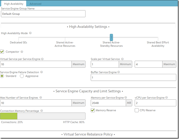
Now I can alter the default behaviour for the SE’s in a deployment
For instance the default memory for an Service Engine is 2048 MB, SSL connections consume alot more memory then regular L4 connections, and therefore we might even alter the memory capacity if we have available. NOTE: The memory limit can be between 1 GB and 128 GB per service engine.
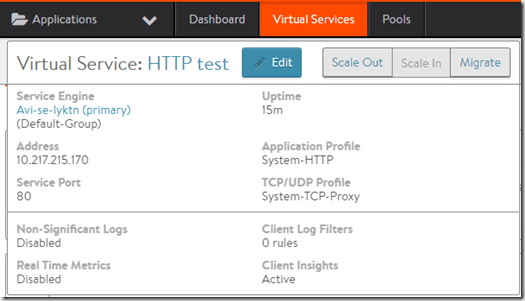
I can also from the service window, migrate the service to another service engine or scale-out or scale-in
Doing Migrate or scale-in will handle all new connections, forwarding any older connections to the secondary SE.
Now we can easily see the benefits of this type of architecture, where we have a distributed management layer and a distributed data plane unlike the other ADCs which have effectivly moved their existing appliance model to a virtual appliance where they suffer from the limited resources they have available.


